| Niki's
Sophia DLG |
 |
| |
|
|
Items |
Specification |
|
Wing length |
1495mm |
|
Profile |
AG mod. |
|
Wing area |
22.6dm2 |
|
Wing loading |
14.5
g/dm2 |
|
Structure |
Glass-Balsa-glass
Sandwich |
|
Portability |
|
| |
| Tail
plane |
Profile |
Rudder : Symmetric
Elevator: asymmetric |
|
plane area |
3.6 dm2 |
| |
| etc. |
Total weight |
280-350g |
|
Radio gear |
4
servos , more than 6 channels |
|
Fuselage Length |
1135mm |
|
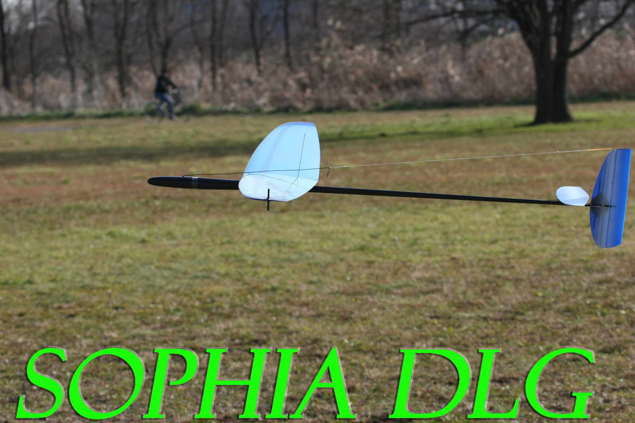
| The veil of the Sophia, a new Discus Launch Glider has been taken out, which is made by the Nan ltd., famous as the maker of Radina DLG, in Bulgaria. The name is the same as the capital city of Bulgaria, since it is one of the best models in Bulgaria. The characteristics of the Sophia as comparing with Radina DLG, its sister model, is summarized as follows; (1) Thin aerofoil profile, (2) wide aerofoil, (longer cord, hence high aspect ratio), (3) Flying tail (all-moving elevator), (4) Reinforcement of fuselage. The model Sophia was developed by Nikolay. It is also a fruit of the improvement efforts by Japanese fliers through its prototyping.
While developing the Sophia, the thin profile was recommended, at the first, such as the AG profile used by the famous FIREWORKS in order to improve the performance of both the penetration and the thermal duration. Since the thinner aerofoil section result in the less lift, therefore, at the second, the wing area must be increased by making chord longer. The wider aerofoil compensates the less lift by the thinner aerofoil section. At the third, flying tail (all-moving elevator) was proposed, because the flying tail is a trend and is expected to improve the performance. The elevator is not a flat, but an asymmetric aerofoil section profile which may result in the high performance depending on the adjustment. As the fourth improvement, the fuselage became a sophisticated one as well as reinforced.
The Sophia DLG is the succeeding model, and not a replacement of Radina DLG. They are rather two models based on the completely different philosophies, and have each own characters. From the view point of their name, I have personally impressions such as a cheerful Radina and and sophisticated Sophia, but the Sophia is rather faster and longer- reach. So the Sophia, the new model would give you more fun, if there is more wider space. (2008.4.4)
|
|
|
|
|
 |
 |
 |
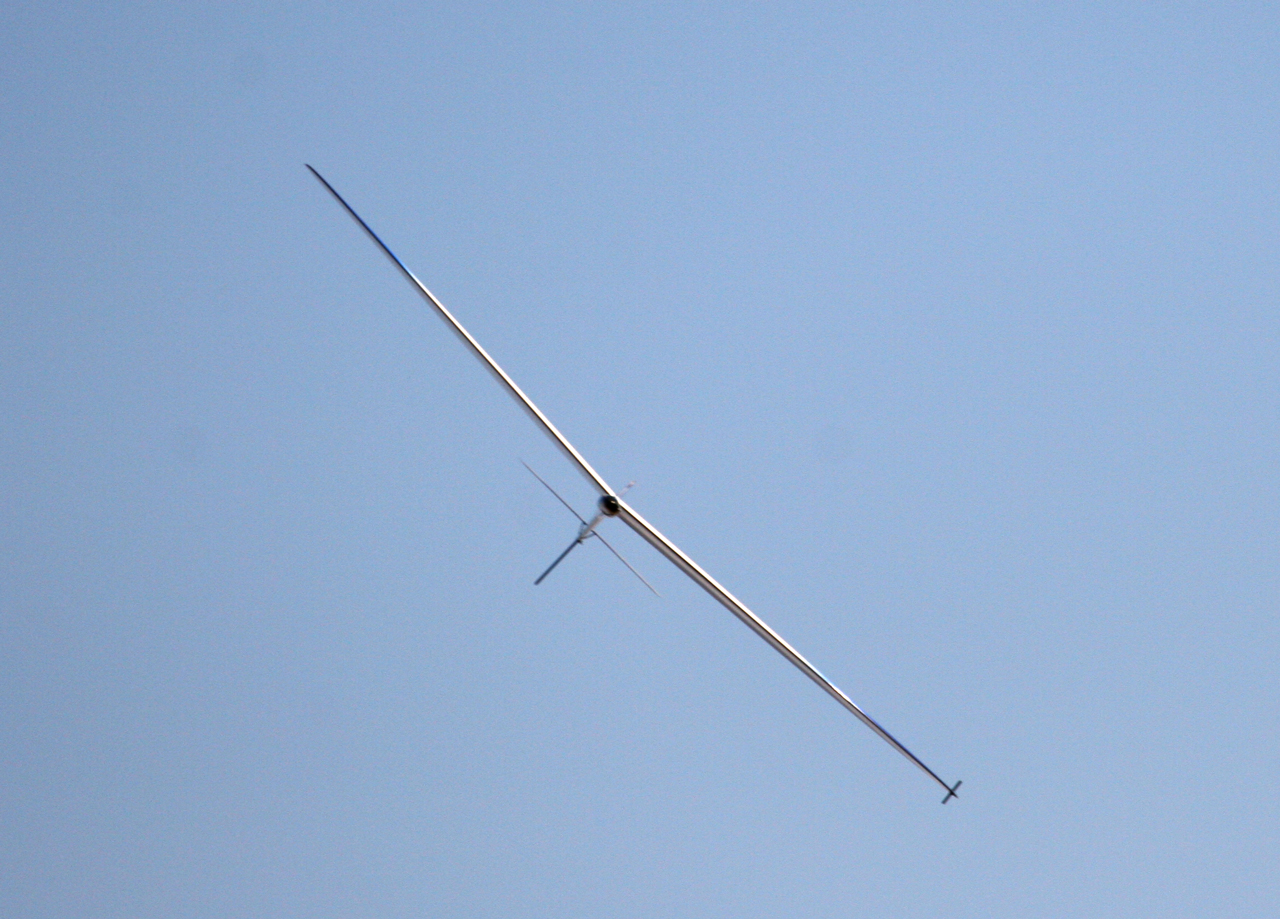
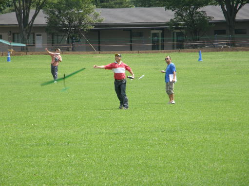
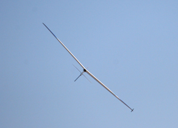
RadinaDLG is long and high reach model than the conventional model. Hence it flies so faster. Sophia is however more than Radina DLG, a model longer and higher reach. The flight technique for faster model seems to be suit for the Sophia.
|
This thin aerofoil section profile is artistic. The thinner aerofoil is, however, inclined to be a more easily warped structure. But Niki's excellent technology enabled an artistic and aerofoil without warp. On the contrary, the sophia is stiffer than conventional models.
|
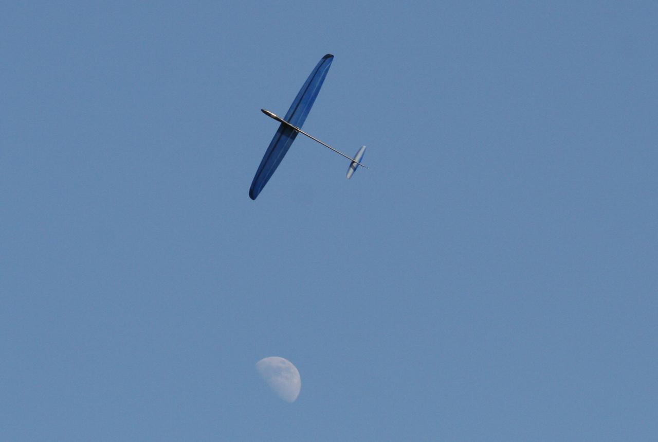
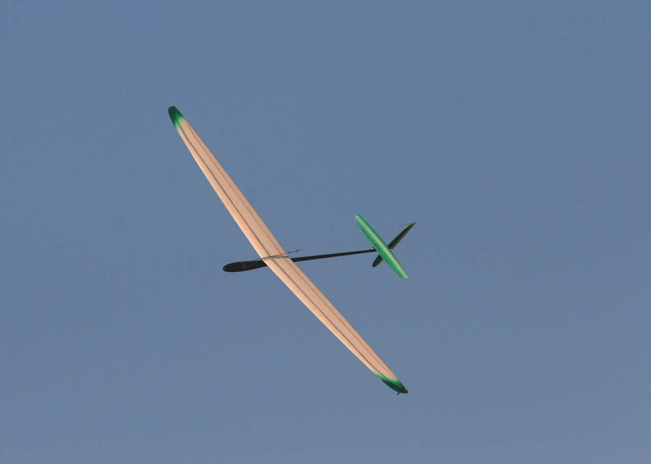
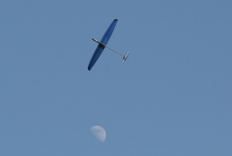
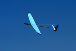
The Blue Sophia of Mr. Kiyose lives in the world higher than 60m (70 yards). It is good for him taste the sweet and bitter by flying the Sophia with Moon as a background. If you see more, click here.
|
 |
 |
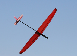 |
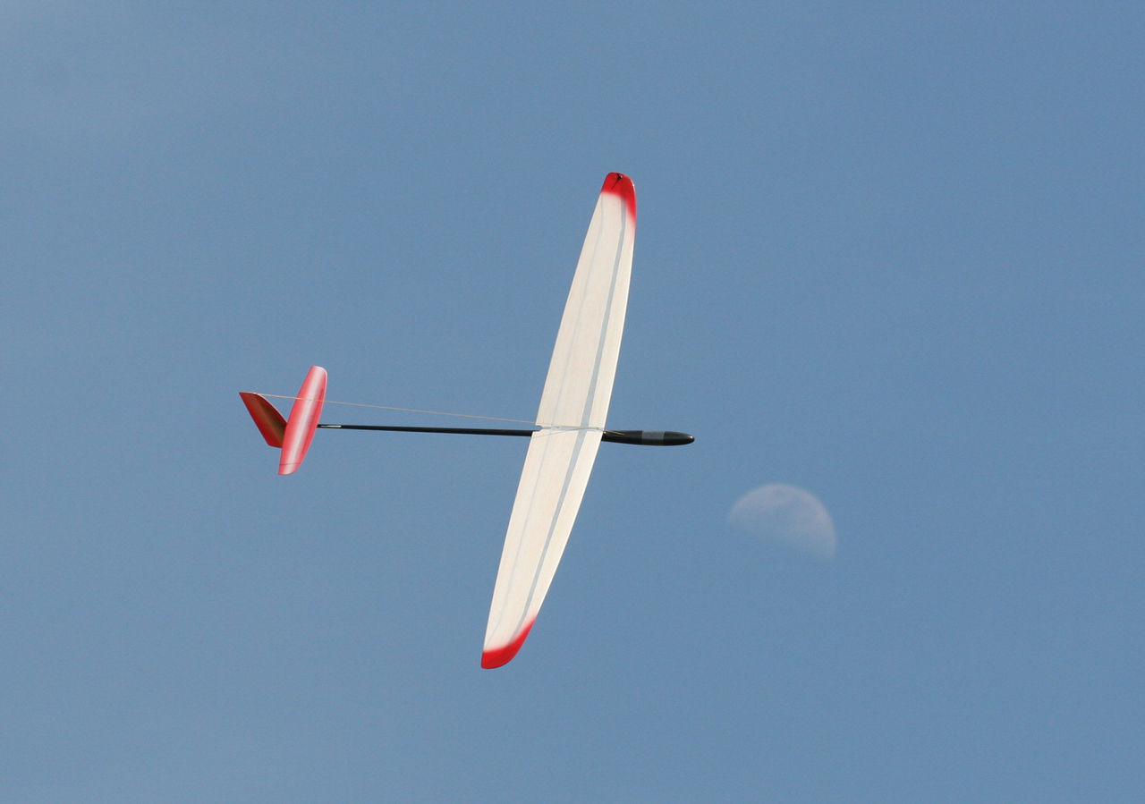
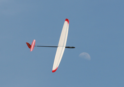
Mr. Yamamoto's red Sophia. The wing tip coated by Crystal red looks so beautiful. The moon is also seen behind the sophia
|
Mr. Yamamoto's Red Sophia is in the approaching course. |
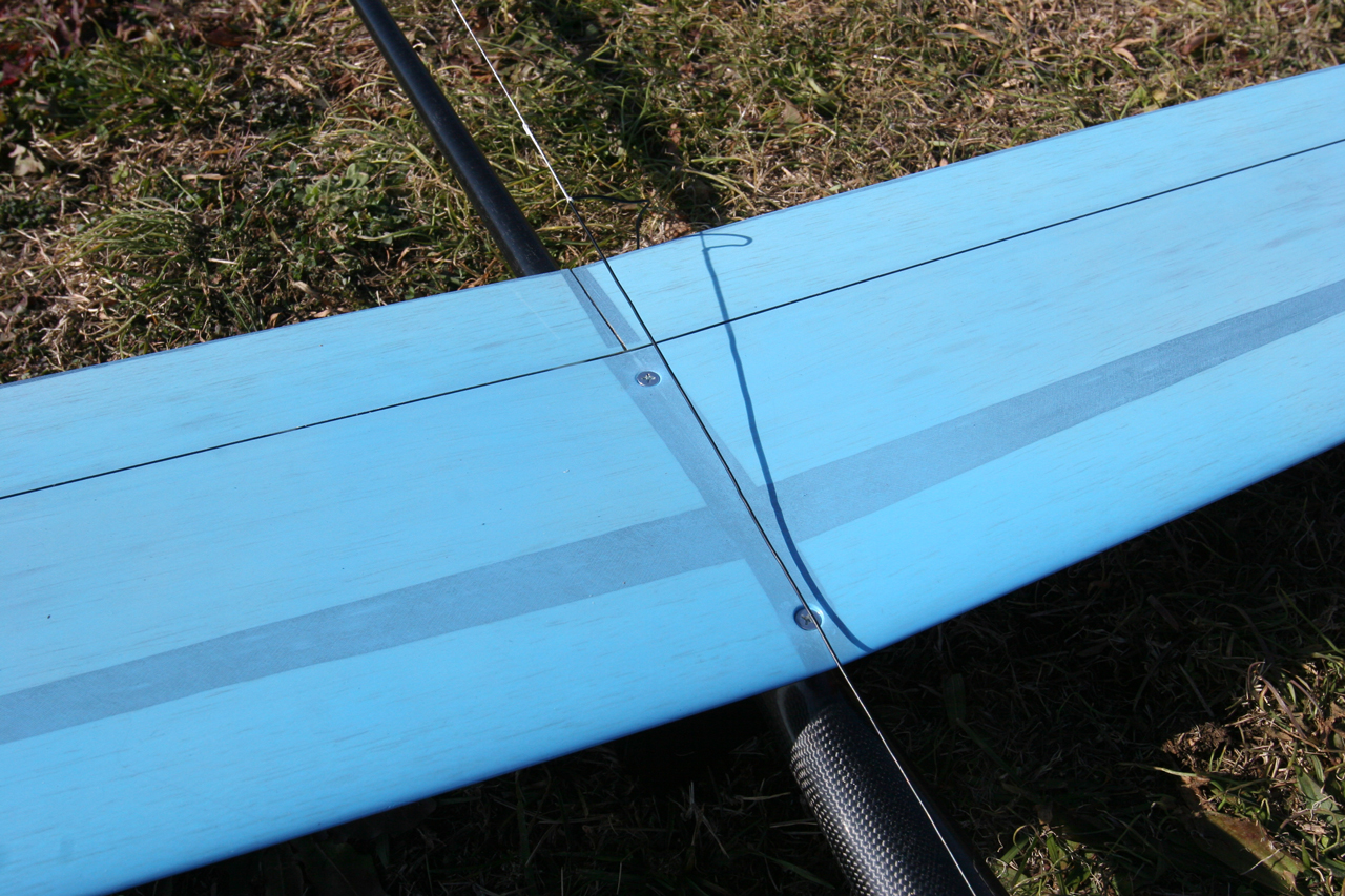
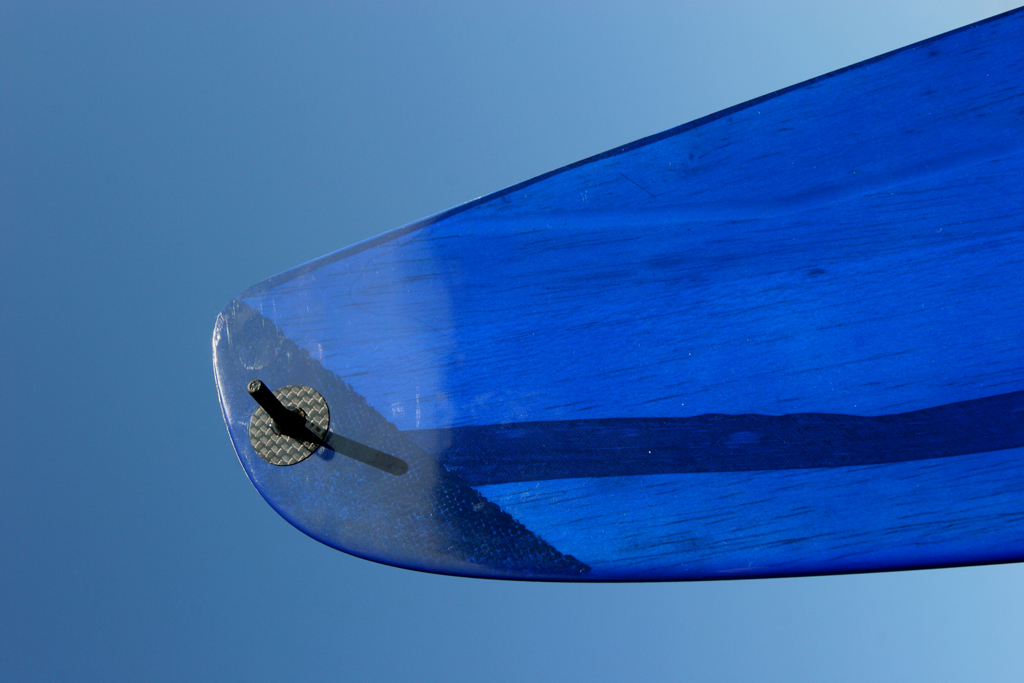
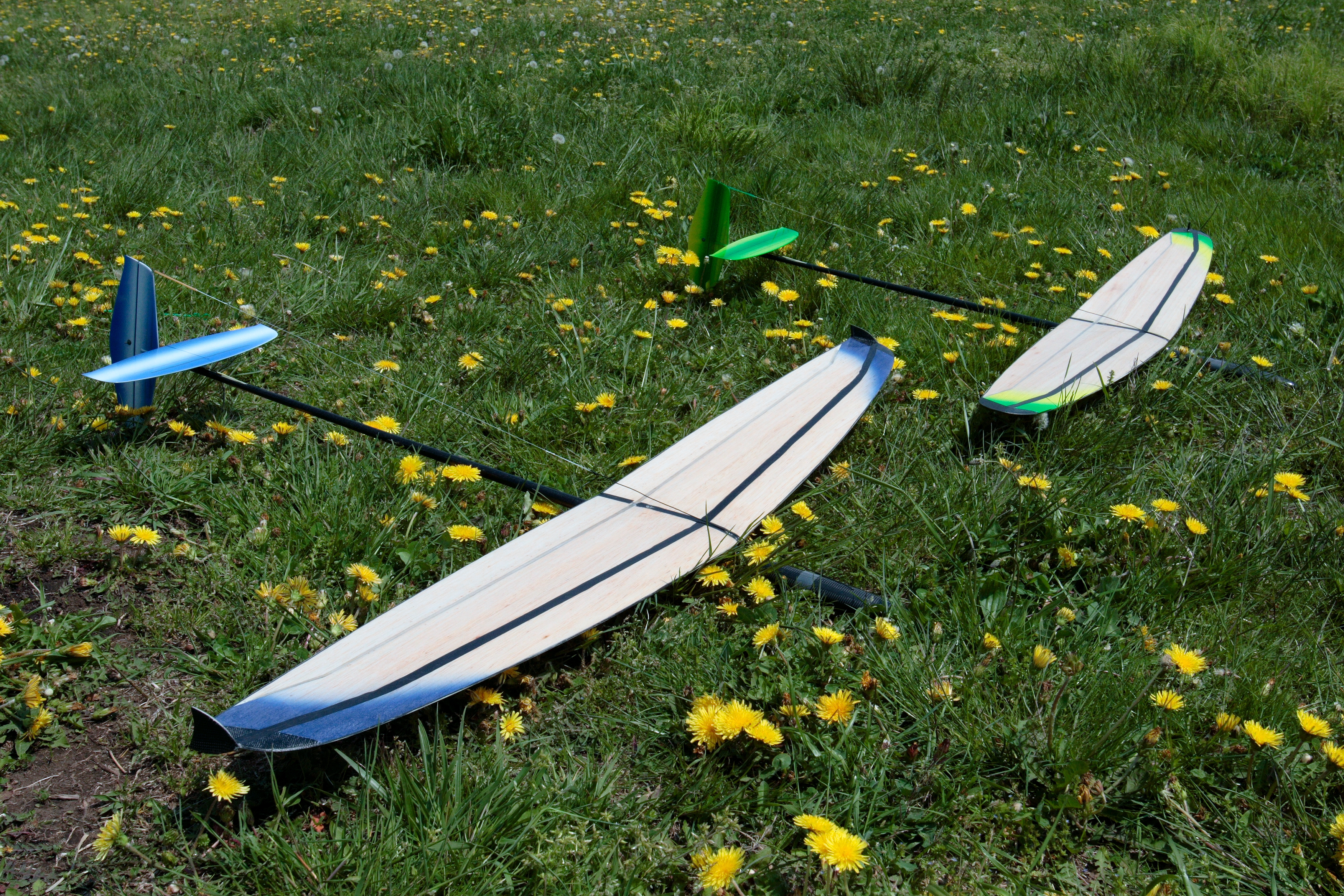
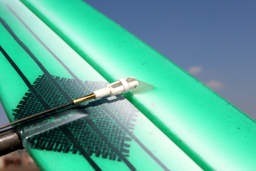
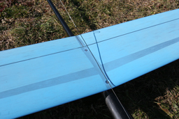
The bottom of wing is also coated by crystal red. The black stripe shows a carbon reinforcement ed spar. The finger can be installed into both sides of tip end for the left hand throw as well as right hand throw. |
 |
 |
 |
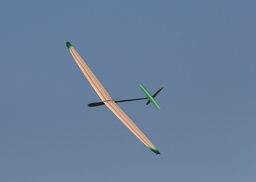
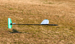
White and Green Sophia was not in the color pattern at the begging. It was added by a strong request from the dealer. Crystal green is so beautiful like a emerald.
|
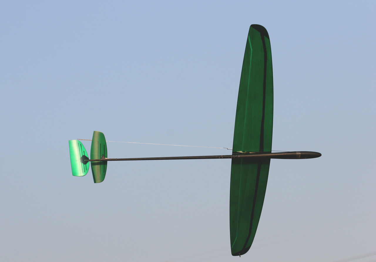
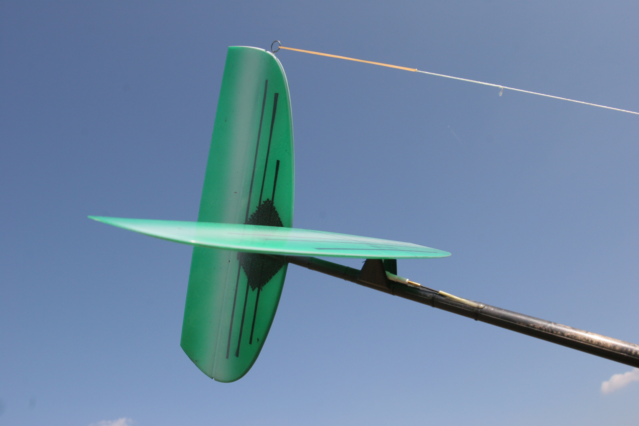
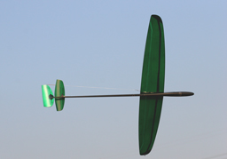
Green Sophia. Sophisticated its front view. |
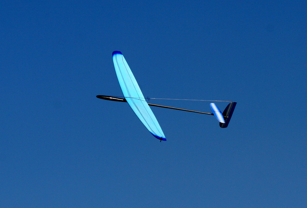
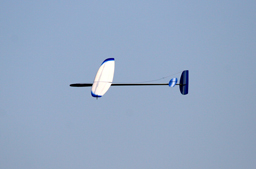
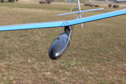
Dark blue and sky blue Sophia seems to be preferred by the European fliers, which is well-suited with the blue sky. It does not melted in the sky. This pattern is used for another model of Nan ltd. |
 |
 |
 |
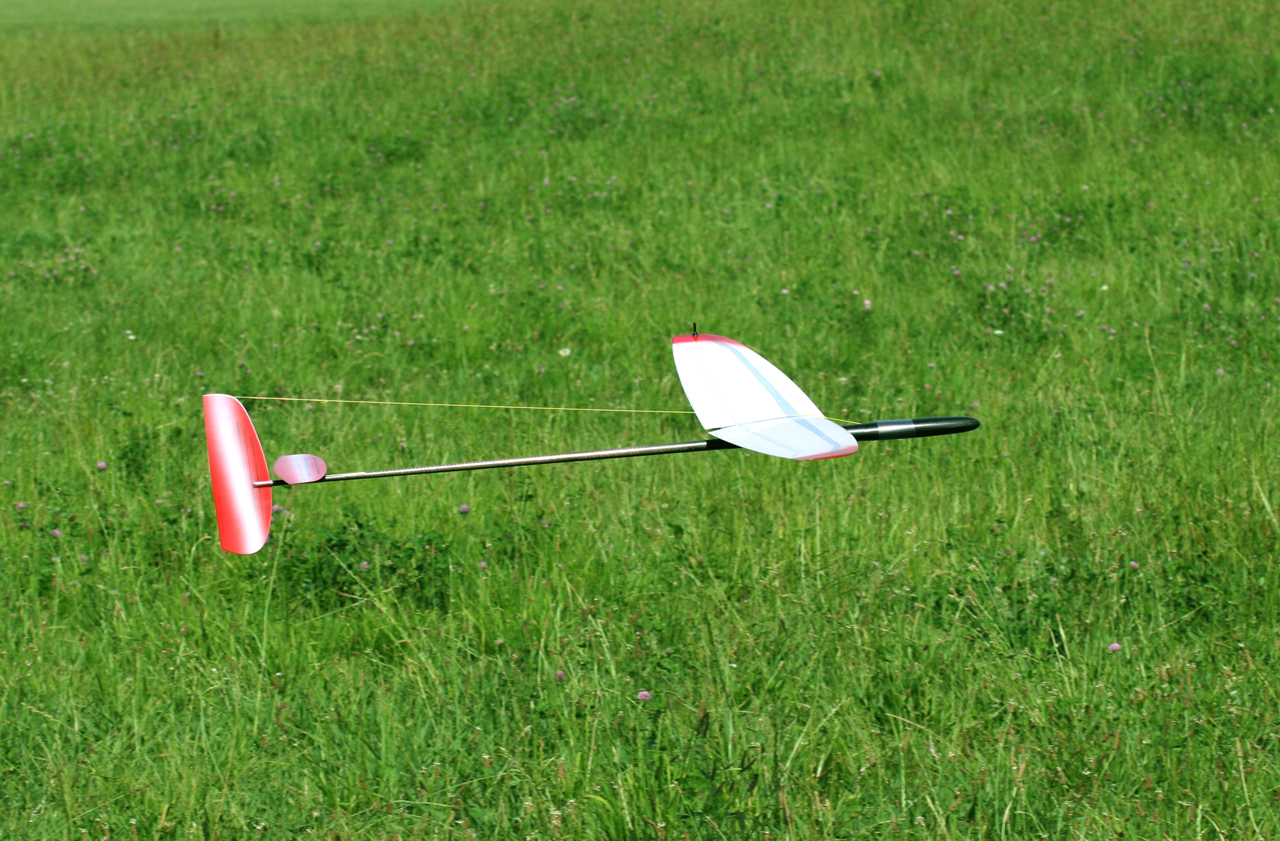
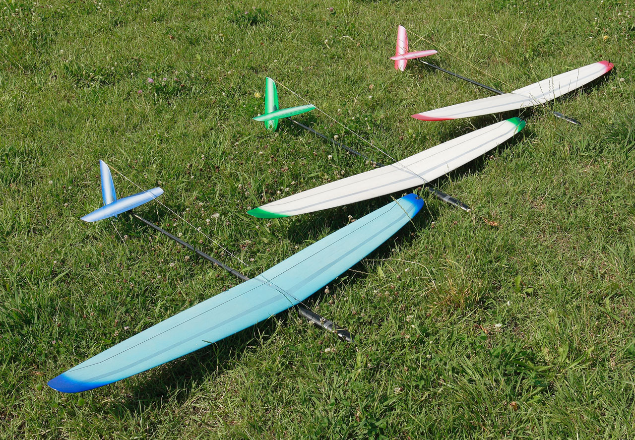
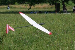
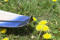
| Red Sophia is in the green carpet of the white clover. |
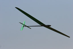
Green Sophia in winter. a green plant on the desert. |
The back side of green Sophia is also crystal green. |
 |
 |
 |
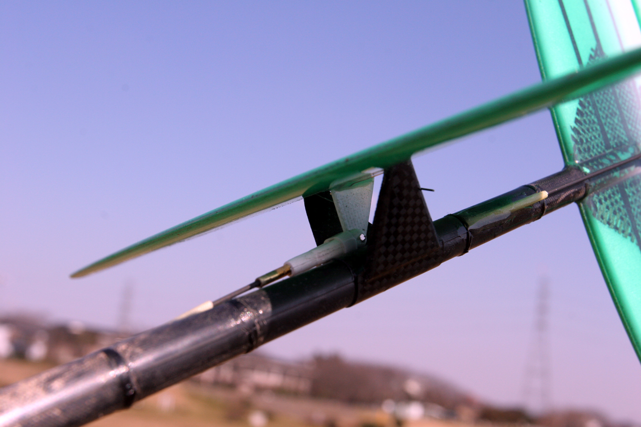
The elevator is all-moving elevator. The aerofoil attack angle is expected to be changed by sifting the neutral position of the elevator. The elevator is not flat but asymmetric which can make lift to the tail of the sailplane. Please read how to use the lifting elevator.
|
Flying tail is inclined to have too much play at the neutral position of elevator. This "play" or small amount of deviation causes big pitching.
The Nan model invented to use a kind of torsion bar in order to remove the "play".
|
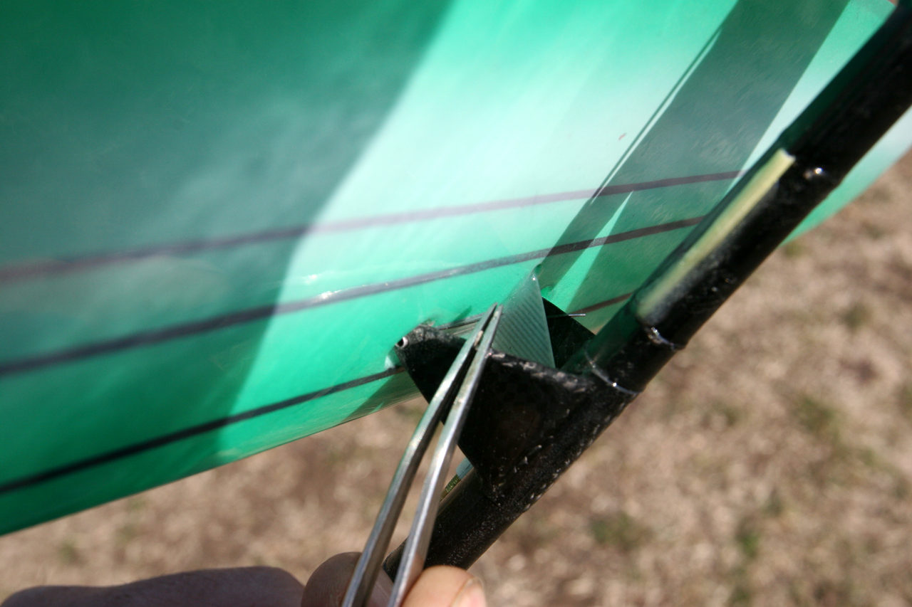
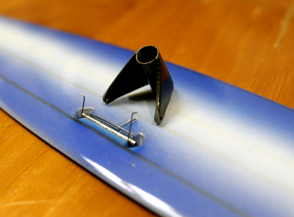
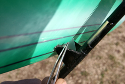
The boom hole was molded from the begging and reinforced by carbon cloth. In case of Radina DLG, the assembling of boom and the fin is a one of tough task. This built-in type fin makes the connection easier. The current fin of Radina DLG has been also replaced by this new fin. |
 |
 |
 |
The linkage of all-moving elevator prohibits the play (deviation at neutral). The guide tube must be adhered with the inside of boom of the fuselage.
|
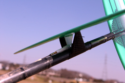
The linkage of the all-moving elevator can be installed by adhering the guide tube with outside of boom of the fuselage, which is an idea by Mr. Kanoh. The guide tube is pulling out an the end of Pod. A proviso, the linkage of rudder is installed in the boom. |
The fuselage is finalized with high quality. It is very right and stiff. Those who make aerofoil by himself will welcome this fuselage. The quality of the fuselage is quite better than the Radina DLG. |
 |
 |
 |
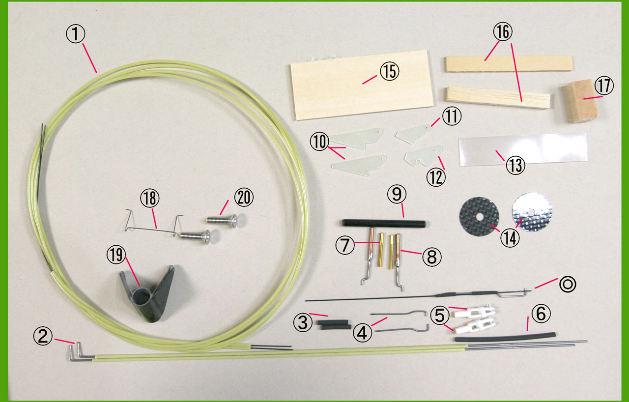
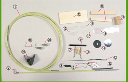
Mr. Hirata supplies a part set dedicated for the Sophia DLG. It would be welcomed by the beginner and those who doesn't want make much garbage for their wives. Mr. Hirata supplies the parts set for Radina DLG. Both are magnificent.
|
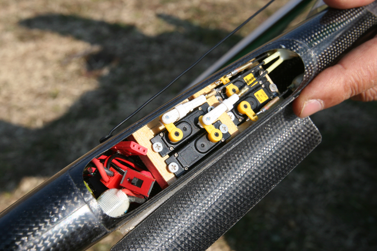
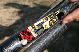
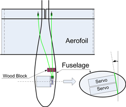
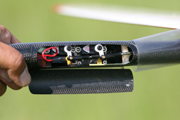
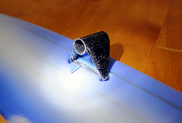
Two servos at the front row are for flapperons, and two servos at the back row are for the elevator and rudder. The back servos must be installed a little lower than the front servos, so that the linkage wire and servo horns do not contact each other. The applicable servo is only TS1002 made by OK Model(Japan), which 8mm thick. The thicker servo than TS1002 is hard to be installed like that.
|
Flapperon servos should be placed at a slant from vertical line, with angle like above picture. The slanting angle of servo would be fixed so that the flapperon linkage wire can move smoothly especially at the neutral position. Two flapperon control guide tube should be fixed by wood block like above picture. |
 |
 |
The wing shapes of the Sophia DLG and the Radina DLG are different from each other. The wing of Sophia is closed to the elliptic wing. The elliptic wing is a ideal wing which has much advantage on the stability against stalling.
|
Another example of installation. Mr. Yamamoto installed 9g digital servos at upper row in the radio gear room to get high torque, which is made by en-Route co This digital servo is 12 mm thick. all of four servos can not be installed. So only two servos were used. The remaining two servo are to be for elevator and rudder.
The digital servo has high torque and few play at the neutral position.
|
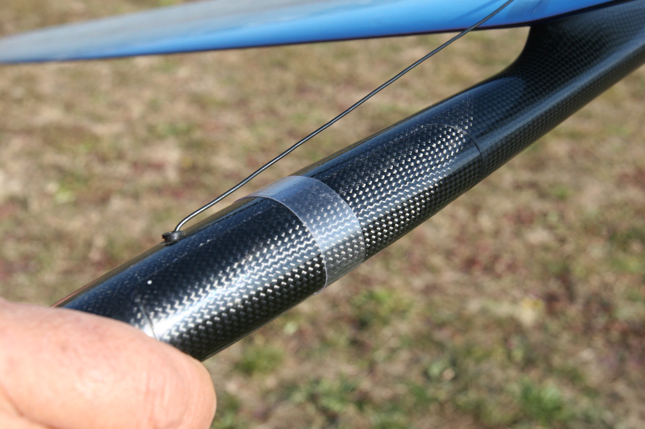
The transparent heat shrink tube is good for holding hatch. It should be paid attention that this tube must be installed before the pod and boom is connected.
|
 |
 |
 |
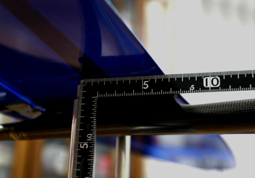
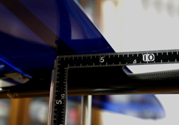
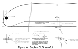
| The Center-of-Gravity locates about 65-80mm from the leading edge of aerofoil. The above picture shows the CG for strong wind. |
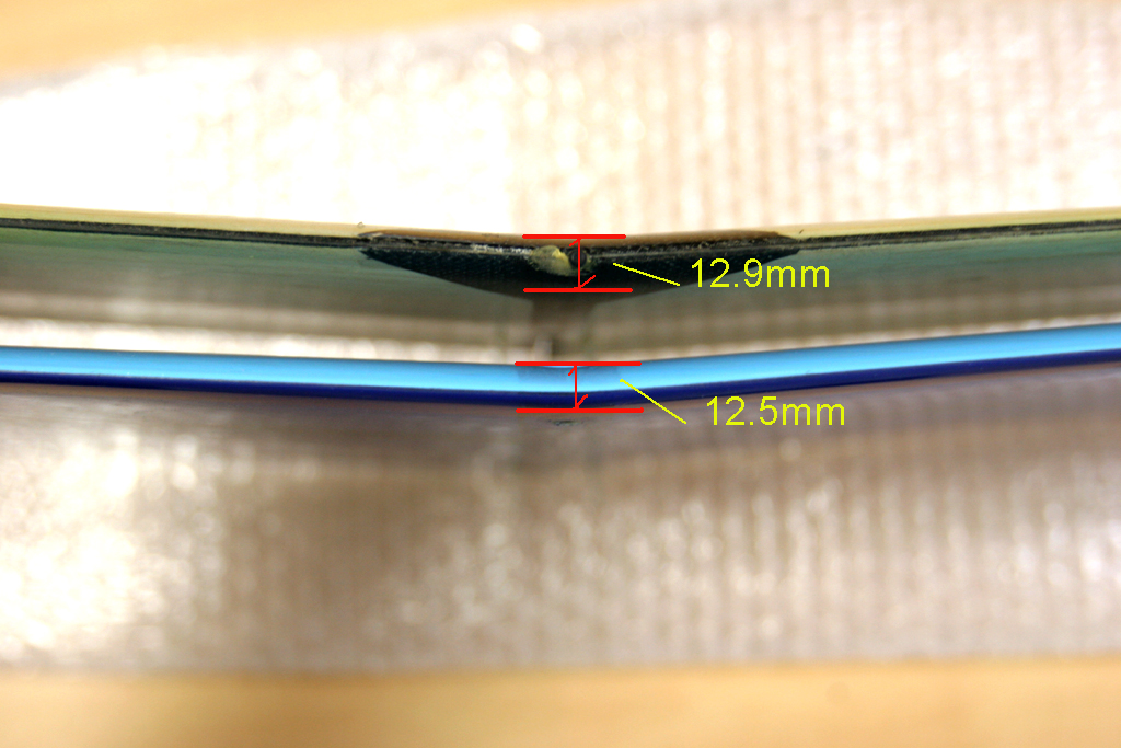
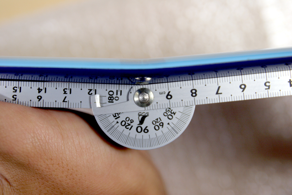
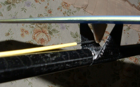
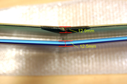
The aerofoil section profile is AG-mod. The thickness of the wing is thinner than Radina DLG.
(The upper wing in the above picture is Radina DLG, the lower is the Sophia DLG.) Taking into consideration that he chord of aerofoil pf Sophia is longer than Radina DLG, theoretical thickness is more than 0.4mm (=12.9-12.5). The trailing edge is so thin like a paper.
|
The dihedral is the same as Radina DLG. The 4 degrees at each side, totally 172 degrees. |
 |
 |
 |
There is a spring like an torsion bar so that no play of the elevator may exist at the neutral position.
|
Since the elevator is pressed toward upward by the torsion bar. the pitching should not occur cased by the play of elevator at the neutral position.
|
The wing of the Sophia is lower-hinged type. There was upper hinged type. The lower hinged wing has advantage for making butterfly brake. Therefore the lower hinged wing is adopted finally. |
 |
 |
 |
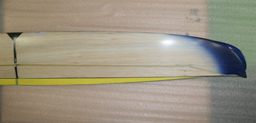
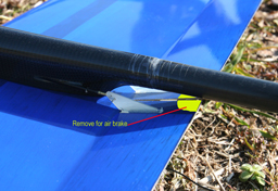
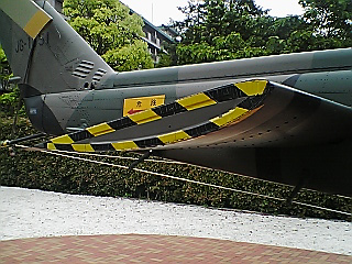
If you want a strong air brake (Butterfly brake), the yellow shaded portion in the above picture may be removed. But the full-size aileron of the Sophia is not designed such that the aileron goes down to the right angle, because the tip end side of the wing is fixed.
|
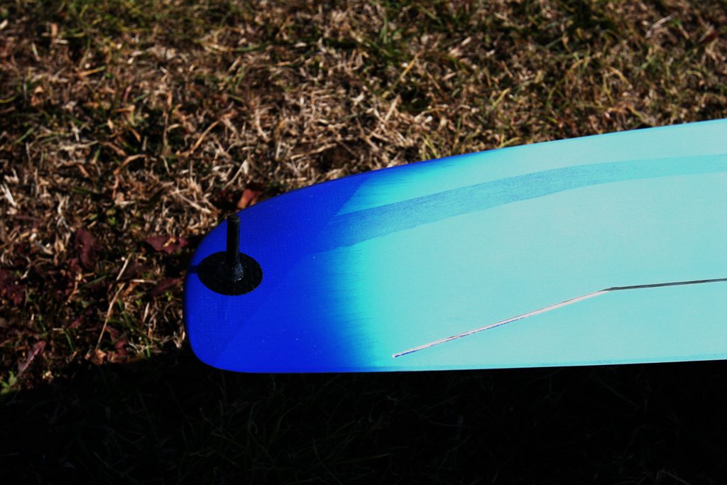
The prototype of the Sophia DLG had winglet instead of the finger peg. But there occurred many accidents caused by destruction of the winglet. The cost for making molded winglet will not balance with aerodynamics merits of winglet. So the conventional finger peg is adopted.
|
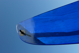
The bottom side of wing at the tip end where the peg is installed. The both sides of wing tip ends are reinforced for installing pegs which enable left handed throw as well as the right.
|
 |
 |
 |
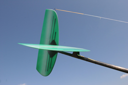
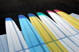
Sophia DLG color schemes. The wing tip end s are coated by transparent, crystal color in every schemes. The wing is molded by the epoxy high purity , results in the tip end with crystal green, red, blue like a jewelry.
|
Available color of the Sophia DLG. Currently 6 patterns are available.
|
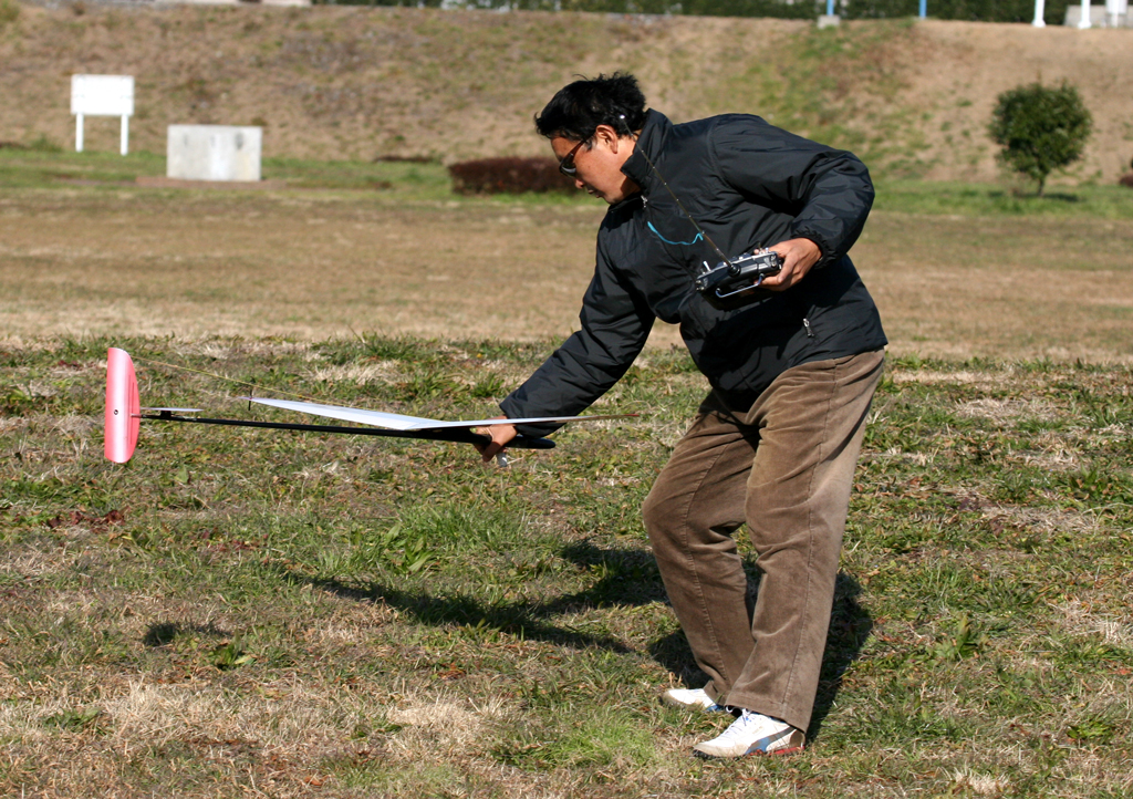
Mr. Kiyose, a Sophia DLG flier. After flight to the moon, he seemed to be much satisfied with the flight of Sophia DLG. It is him that made the flight to the Moon shown above.
|
 |
 |
 |
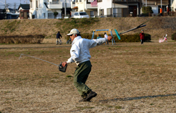
Mr. Hirata, a well-known flier. I always ask to assemble and repair DLG. His technique is magnificent. Someone says that there is a vendor machine, if you insert 100yen coin, then the damaged Sophia would be fixed by Mr. Hirata in the machine.
|
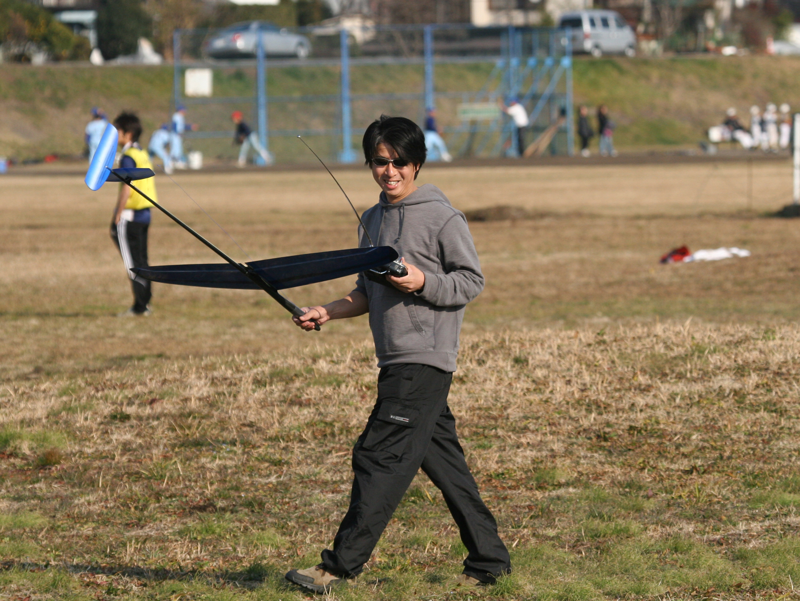
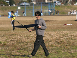
Once, Mr. Yamamoto hold the Sophia, no one can stop him like Karaoke. Mr. Yamamoto keeps throwing the Sophia so that he may spend all of his time, every time he visits the airfield.
|
Mr. Kanoh, one of the leaders of DLG in Japan. He gave many comments during the improvement of the design and prototyping. (the picture was quoted from KIMURA air craft. In addition, Mr. Kanoh took a picture of her at Jyogashima, beautiful site in Japan. |
|
| Wing: |
(1) Structure
a. Molded aerofoil
The aerofoil of main wing is molded as the Radina DLG is, the thickness of Sophia DLG is marvelous. Though the FIREWORKS is highly evaluated as competition model whose wing is also thin, the quality of the wing of FIREWORK seems not always good. The some wing of FIREWORKS seems to be sometimes warped or the stiffness seems not to be enough. The Sophia DLG, however, has never warped and has enough stiffness. It must be said that the Niki's technology of manufacturing aerofoils is excellent. The wing is finished gelcoat colors that is transparent so as to see the balsa wood base. The leading edge and trailing edge is reinforced by carbon robing and is very keen just like a razor. The model made by Nikolov is robust as well as light. I have never heard that the wing of Sophia as well as Radina DLG was broken due to the hard launch even with the full swing.
b. Lower hinged aileron/flapperon
The aileron/flapperon has been designed to be a lower hinged. On the other hand, the Radina DLG has upper hinged aileron. It makes sense that the aileron was pulled by the aileron horn attached at bottom side of aileron in case of upper hinged wing. But the wing hinged at upper side does not enable flap to go down deeply at almost 90 degrees as a strong airbrake. The air brake was not required in the DLG/HLG thermal duration competition. The F3K, however, requires the air brakes for saving working time, since the DLG must be launched several times within a specified time and the summarized flight time is competed within a time frame. In this case, it is seen such a flight technique that DLG would be stalled in the air by a strong air brake and would be picked up by a hand, and would be launched. So the benefit of lower hinged model is superior to the upper hinged model, even if the upper hinged linkage is reasonable. We have tested if there is no problem, when the lower hinged moving wing would be pulled at the bottom side of moving wing. The result is flapperon of Sophia hinged at lower surface does not go down because the skin hinge was too hard to angle flapperon at enough angle, even if the trailing edge on the fuselage is cut. The inside of skin hinge must be abraded. We confirmed anyway that the Lower-hinged wing works well.
c. Flexible aileron (Elastic Aileron)
The flapperon fixed at tip end is one of characteristics of Radina DLG, which is also used by the Sophia DLG. In case of the Sophia DLG with lower-side hinged wing, the flapperon end is also hinged at the lowered side. The aileron end is cut athwart. Fixing aileron end prevents from flattering in diving at high speed from high altitude. It makes the stable flight as well as preventing to break the gear of servo. From the view point of aerodynamics, the camber is strong at the root of the wing and is gradually relaxed along the elastic aileron. There is so called the Wash-out effect. Because the air flow is guided from center to the end of the wing tip, the air flow cause buoyancy even at the low speed. It is expected to result in that the tip stall is suppressed effectively. The technology used by both Radina DLG and Sophia DLG is simple and robust in its structure. The simple is the best. Some open class model such as F3B/F3J models equips Giga flap, whose effect would be similar. |
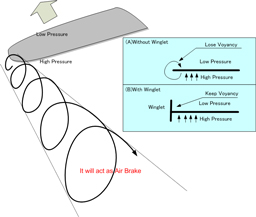
d. Finger Peg and Winglet
The prototype of Sophia DLG has winglet shown by the right picture. This winglet is also used as the finger peg, which is similar to that of FIREWORKS. The effect of winglet is to suppress the turbulent at the wing edge shown by the right figure and to reduce a braking effect. In addition, winglet keep the pressure difference at the wing tip end, therefore preventing from loss of buoyancy at the tip end. Some dictionary for aerodynamics says that the winglet improve energy-effect by reducing the vortex at the tip end or by shifting it vertically and decrease the drag force caused by air resistance. It is, however, unknown that the winglet has significant effect to small air plane such as Sophia DLG. It is true that the winglet can be used as a finger peg. The other effect is not proven. The costs to make winglet will not be small in the course of manufacturing process at all. Due to the expensive finger peg, the total cost should not be high. The winglet will be an obstacle for transportation. Finally, we decided that Sophia DLG does not equip any winglet. We have asked to make Sophia DLG without any winglet, at least for models exported to Japan. We have no intension to say objection to equip winglets to Sophia DLG for other countries.
|
 |
 |
(2)Aerofoil Profile
The Aerofoil cross section profile is AG mod. The AG profile is designed by Mark Drela and used by many HLG and DLG which is known as thin type profile. The thin profile, which is typified by the HN-Profile, by Herbert Nober in the F3B, lead to excellent performance in both the penetration and the thermal duration. Because the Sophia DLG adopted AG for the aerofoil cross section profile, Sophia DLG can penetrate and raise its speed steeply, anytime its elevator goes down, while it surfing on the thermal at slow speed. It also transfer from penetration mode to thermal mode, it can reach to the slow speed appropriate to thermal circling, only if you have its elevator up. The Sophia DLG covers wide range of speed. Those model adopted SD series profile fly slowly even if the elevator goes down. In other words, it is designed to fly slowly. (Of, course, the speed would be increased, when diving steeply.) Since the cruising speed of Sophia is little faster than SD series aerofoil, we must change how to fly the model, when we fly the Sophia DLG, the new DLG in order to induce its maximum performance.
|
(3) Flying tail
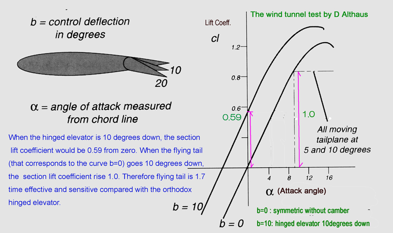
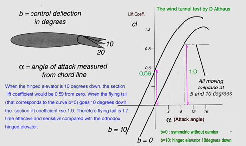
Another characteristics of Sophia DLG, is that Sophia DLG adopts "a flying tail". The aliases of flying tail are "all-moving tail plane", "Pendulum elevator", it is sometimes thought to have aerodynamic advantages over orthodox hinged elevator and fixed tailplane. "The Model Aircraft Aerodynamics" written by Martin Simon introduced some results of interesting experiments by D Althaus. The right figure shows the result of the experiments by Mr. D. Althaus that investigated the difference between all-moving tail plane and partially moving tail plane of hinge type. THe reason that the flying tail has advantage to the hinge type usual tail is as follows;
a. Flying tail with 10 degrees causes 1.7 (=1.0/0.59) times higher effectiveness and sensitivity than the orthodox hinged elevator with 10 degrees. In order to get the same effect as that of flying tail with 10 degrees, the orthodox hinged elevator must go to about 17 degrees. In case of actual plane, the load on to the servo motor can be decreased, it must be advantage. However, in case of model airplane, the small amount of displacement of flying tail cause large gliding angle change compared with hinged elevator. In other words, the flying elevator must be of sensitive. Therefore the looseness must be remove completely caused by unfixed control harness. In addition, exponential curve should be applied for elevator movement by the computer radio control system.
There is another difference between flying tail with 10 degrees down and the hinged elevator with 10 degrees down. In the right figure, the curve of "cl(section lift coefficient) vs. attack angle" moves toward left when hinge angle goes from b=0 to b=10, in case of hinged elevator. The two curve indicated by b=0, and b=10 are almost the same with each other. The curve moves toward left upper while the angle of hinge goes from 0 to 10 degrees. In case of the curve with b=10, the model would stall earlier the case b=0, by small amount of attack angle increase. There is another curve that is called by "drag coefficient curve; Cd". As attack angle increases, the drag force caused by drag would minor to the resistance force caused by the aerofoil profile. On the other hand, the section lift coefficient curve does not move as the attack angle increases. As the attack angle increase, the cl: section lift coefficient increase proportionally. In other words, the resistance force caused by the hinged tail would not occur in case of flying tail. This is the big advantage for the model airplane. The conclusion is summarized right column.
There are both discussion on flying tail for model airplane. Someone says flying tai is better than the orthodox hinged elevator, sometime opposite. Sophia DLG allows both type of tail planes.
|
(CONCLUSION)
The elevator is a kind of brake. The resistance force of flying tail is less than or equal to the orthodox hinged elevator. It is the biggest advantage.The flying tail is more sensitive than the orthodox hinged tail. The looseness caused by control mechanism must be removed completely. Otherwise it will cause pitching. In addition, Exponential curve around the neutral position in the radio control system should be applied for "stick movement vs. flying tail displacement" in order to avoid from sensitiveness of flying tail control.
|
|
(4)Standard trim
a. Center of Gravity(CG)
CG locates 65-72mm from leading edge. (the right hans side is the nose of Sophia DLG.) However, there is not a so-called standard trim. It is enough to set CG to the certain location depending on each flier favorite and set trim according to this CG. In the picture, CG locates at 65mm. But this is the setting for windy day. The CG locates more back word, the it is easier to find out thermal.
|
|
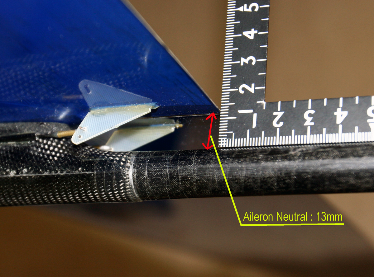
b. Aileron neutral
The aileron of Sophia is full size aileron. There is no fixed portion at the trailing edge. The neutral position of aileron can not be known by some reference point such as fixed trailing edge. The best way is to measure the distance from the top of fuselage boom to the trailing edge end. It is 13mm in usual. Otherwise, move aileron in order to find out the smoothest angle by touching the bottom surface of the airfoil by finger.
|
|
c. Aileron differential
When selecting flapperon model in the Radio control system, the differential aileron can be set. The displacement ration Upper: lower = 2:1 in usual. However 1:1 maybe a challenge. The differential aileron is required due to the asymmetric aerofoil profile. 1:1 can not be acceptable in theory. Setting 1:1 is based on the experience. It is up to you.
d. Aileron Rudder Mixing
Aileron Rudder Mixing is for cancelingyawing caused by left aileron
dropped when the airplane turn right and vice versa. When it is a calm day, this mixing cause a problem. When both the rudder and aileron have effect on a calm day, then effect might be excessive. The model will lose buoyancy at the aerofoil end. The mixing ratio form Aileron to rudder maybe 60% at most. When
yawing is too much, you are going to turn right, but nose of model turn left and fly straight forward or slightly turn left, then both differential aileron and aileron mixing must be used appropriately.
|
| Elevator |
UP 8 mm, Down 7mm |
| Rudder |
Right 10 mm, Left 10 mm |
| Aileron differential |
Up 10 mm, Down 5 mm(2:1)
Up 10 mm, Down 10mm(1:1) |
| Aileron Rudder Mixing |
60% |
| Thermal flap (camber) |
1mm down ,
(Elevator: a little down) |
| SAL(Launching) flap |
2-3mm up |
| CG |
65-80mm from leading edge |
| flying weight |
290-320g |
|
|
|
|
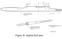
| Fuselage: |
(1)Pod stiffness
Sophia DLG Fuselage is Pod & Boom style. The pod of Sophia DLG might be the most stiff and highest quality among the pods available as of now. The servos are installed vertically in case of Radina DLG. For the Sophia DLG, the servos are installed horizontally. It looks like turn Radina DLG 90 degrees left. The pod of Radina DLG is made of Kevlar and Carbon cloth and flexible. The pod of Sophia is made of only carbon cloth and stiff. Though it loses flexibility, the Sophia's pod is made of enough carbon and to be robust.
(2)Boom
The same boom is common to both Sophia DLG and Radina DLG. The diameter of Sophia pod end is slightly smaller than the inner diameter of boom end. So the end of the boom must be cut a little in order to make the diameter wide at the end of Boom.
|
(3)Installing servos
The inner room in the pod is wider than it looks. But the installable servos are limited. The best installable servo is TS1002 8mm thick. When servo is thicker than 8mm, it can not be installed without difficulties. The two servo installed at front of pod are for ailerons, rear servos are for elevator and rudder.
The servos are installed in the asymmetric manner. The linkage must be adjusted so that it returns at the neutral position when the stick is released.
a. Aileron Servo
The servos are installed horizontally. However, it is not turned at right angle, but a little slanting, so that the resistance between the control rod of right aileron and guide tube would be removed completely. Two control rods are fixed to the inner surface of fuselage pod by the wood tip.
b. Elevator and Rudder Servos
Rear two servos would be installed at a step lower so that the control rods for ailerons would not be interfered with each other.
|
|
|
|
(3)Linkage
The linkage method is not unique. The right drawings introduce how to assemble the Sophia DLG using the parts set provided by Mr. Hirata. There is no instruction for Sophia DLG provided by the manufacturer. Please enjoy assembling Sophia DLG by your own way.
The most important key point is the linkage of the elevator among linkages. The Sophia DLG has the flying tail. Please remove the looseness of the elevator linkage completely. The control harness tube should be adhere to the inner surface of the boom by using low viscosity instant glue. Otherwise, the linkage tube should be fixed on the outer surface of the boom like the method by Mr. Kanoh.
(4)Receiver
As for the receiver, Small receiver such as JETI REX5, GWS and so on , may be used. The smaller the better.
|
 |
 |
|
|
| Flight: |
(1)Attainable Altitude
The average reachable altitude is about 40-50m high at launching. If skillful pilot launch Sophia, it would reach 50-60m depending on the wind condition. The attainable altitude depends on the flying weight of Sophia DLG. The total weight of Sophia DLG should be 290g at least. Then a pilot is enabled to accelerate model easily at launching , the model keep climbing without loss of speed. When the flying weight is too light, the Sophia DLG would stop climbing during launching. The heavier Sophia DLG can not always get higher altitude. The point is that the resistance should be minimized, by positioning CG at the right location. The aileron trim at launching is about 2mm up (negative). The Sophia DLG does not make friction noise at launching, which shows that the friction of Sophia DLG is small enough. The Main plane of Sophia DLG is very thin, but without torsion, though the main plane of FIREWORKS has sometimes torsion a little. The tail plane is made of foam with glass fiber reinforcement. thus very light and stiff.
(2)Thermal duration
The Sophia DLG might not be slow flying glider. While it flies slowly, Sophia DLG sometimes loose speed. Therefore the best way of flying Sophia DLG is to keep high speed and seek thermal. When you find the thermal then turn quickly and get altitude, and run wide area to find out a thermal. And repeat this process. In the big thermal, any model can get on the lift. It is shown by the picture in this page, "play with moon by Mr. Kiyose". When there is no thermal and only the beam wind is blowing, it is a challenge if the energy of beam wind can be changed to lifting energy. The Sophia DLG is a harmonized model from the view point of performance (penetration and thermal duration) and cost.
(3)Asymmetric elevator
The elevator is asymmetric profile and is neither flat panel nor symmetric profile. WHen the prototype was tested the rudder was also asymmetric. The rudder profile was changed to symmetric, because it did not fly straight forward at neutral position of the rudder. The elevator remains asymmetric. The problem is which side should be up. The normal mounting is the same as main plane. The reverse mounting is just like the right picture. The tail plane of helicopter is upside down compared with mail plane, as shown by the right picture. The YS-11, Japanese Domestic turboprop jet plane has the similar flying tail upside down. It is not known the reason that the tail plane is mounted upside down, because few information. The following table shows advantage and disadvantage of the normal and the reverse.
comparison |
the normal tail plane |
the reverse tail plane |
launching |
The elevator works to make the nose down. So, the attainable altitude might be lower than the normal case. |
The elevator works to make the nose be up, as the speed increases. So, the attainable altitude might be higher. |
level flight |
The flight path inclines downward.
Total area that contribute buoyancy is bigger than the reverse. So thermal duration performance might be improved.
The control becomes easier, because the nose is suppressed, when the speed increases.
|
The flight path inclines upward.
The model would be sensitive to the thermal.
On the other hand, the resistance also increases and the speed inclines to be slower. |
|
 |
|
|
| Technical Notes: |
| Prior to the production of Sophia DLG, Nikolay made a prototype and send tem to us for testing and evaluation. The prototype had the winglet and upper hinged aileron. The location of pivot for flying tail was located backward compared with current model. We have joined to the activity of Testing and Evaluation process and made feed back to the maker. It was exciting experience for us. |
|